
The A-frame ball joint is the meaty ball joint sat atop the rear axle on all the older coil sprung Land Rovers.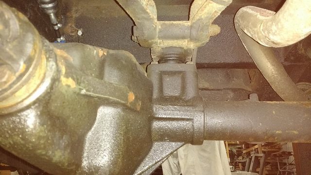
It allows the back axle to pivot about the joint relative to the upper links (which, cunningly, look a bit like a capital A, hence A-frame):
What it doesn’t do is let the rear axle move laterally, or pitch about the lower link bushes. This is quite useful if you ever go around corners. Or brake. Or accelerate.
Usually if the ball joint has got a bit of play it makes itself known by a ‘clunk’ when going from acceleration to overrun, or vice versa. The slight play allows the axle to rotate about the lower link bushes.
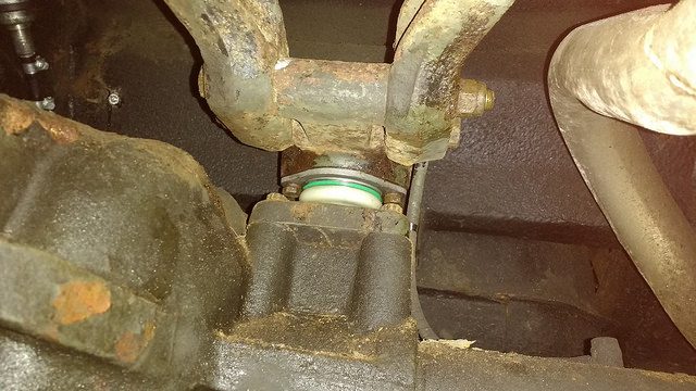
The one fitted to the 127 didn’t have any play in it, yet, but the rubber boot that’s supposed to keep water and crud out was damaged. The ball joint will fail pretty quickly once it gets full of grit, and I’d rather fix it now than have that annoying clunk show up when I’m hundreds of miles away and in no position to fix it – it’s not a roadside job.
There’s not much load going through the joint when the Land Rover isn’t moving, so it can be replaced without too much disassembly with the wheels still on the ground.
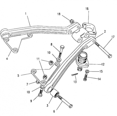
The cone part of the joint is seated on the axle. The other half of the joint is pressed into the snappily-titled ‘fulcrum bracket’ (part 16 in the above diagram). This bracket is bolted to the two upper links. Starting point is removing those two bolts.

The exhaust was somewhat in the way of the rearmost bolt. Jacking the chassis up a smidge under the rear crossmember sorted that out. Looks like this picture was taken in the 70’s, it wasn’t. I should really use a proper camera for this rather than my phone…

Once the two upper link bolts are removed the axle might move a bit – the road springs aren’t held exactly parallel at each end, so there’s a slight moment applied to the axle.
This is a Salisbury axle, as fitted to long wheelbase models. The bracket for the ball joint is bolted to the axle casing on these. With the upper links pushed out of the way, access to the bolts holding the bracket to the axle is possible with a breaker bar.

It’s a bit different on a rover axle, the tapered ball joint seat is integral to the axle casing on those:

Compare that with the Salisbury:

On both types of axle, access is pretty tight to get a socket onto the castle nut that holds the ball joint to the axle bracket. It can be done with a 30 mm spanner depending on brand, but I’d rather do it on the bench with a socket if possible.
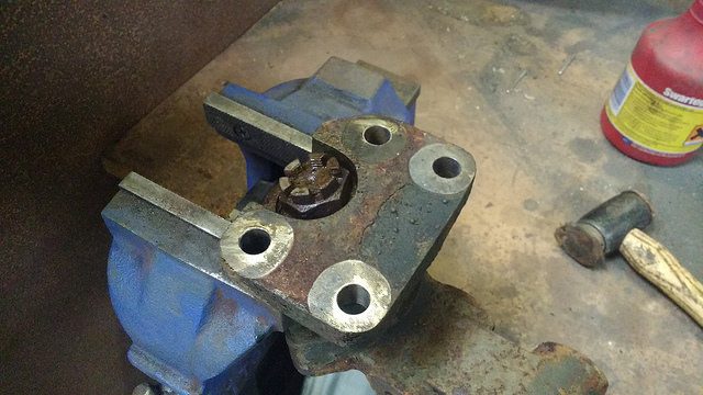
For that reason, I removed the bracket assembly from the axle.

Quite a thin-walled 30 mm socket is required to fit into the recess around the castle nut.

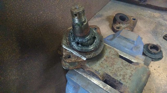
With the nut cracked (ouch), the ball joint should come out with a quick tap from a hammer.
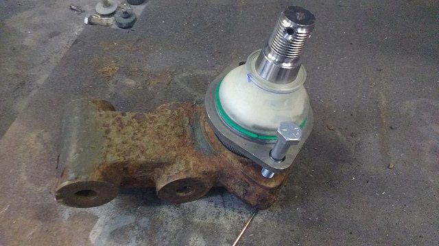
That leaves the other half of the ball joint attached to the fulcrum bracket.

There are two bolts holding these two parts together, but as far as I can tell they’re really only there as a locking mechanism. The load is transferred by a pretty hefty interference fit between the ball joint and the bracket. You can actually buy these two parts as an assembly, as without a press or man-size vice it’s a challenge separating them.
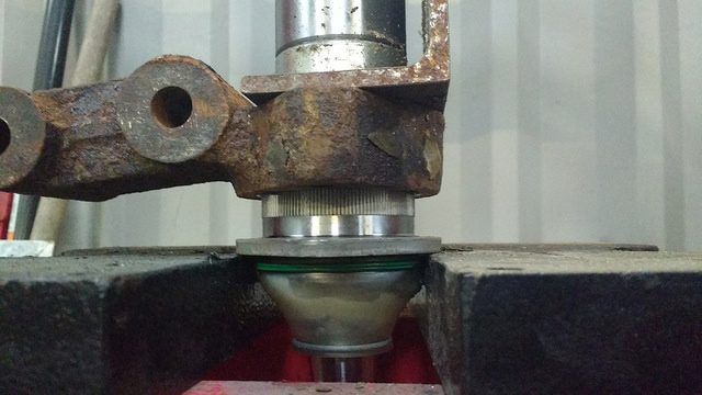
With the two bolts removed (5/16″ UNF in this case, pretty sure it’s M8 on later models) the two tabs on the ball joint can be cut off to give something to bear against in the press.
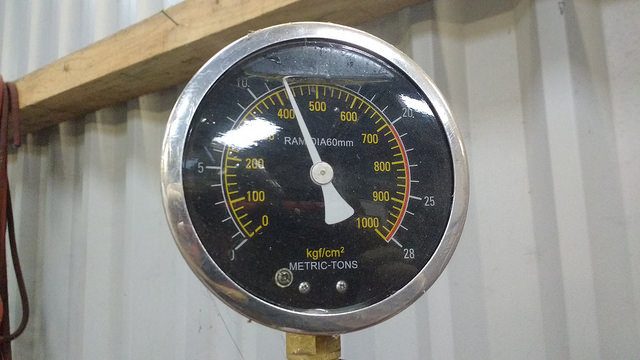
This one let go at a modest 7 tons. Yes, I know that a ton is a unit of mass, not force, but no-one seems to have told the guy that made the gauge on this press…

In a final act of defiance, when the ball joint popped out it landed on and broke my convenient bench-side dustpan. Touche, ball joint, touche.

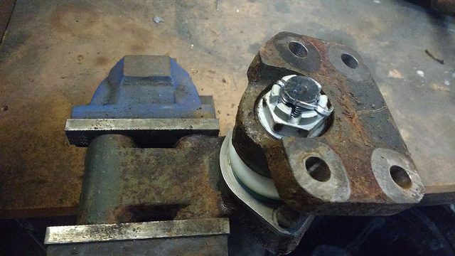
The new joint can then be pressed into the bracket. This particular one’s a Lemforder ball joint – it’s not worth buying a cheap one, it won’t last and you’ll end up doing the job again.
A long bolt can be used to make sure the joint is aligned with the bolt holes in the bracket. As long the joint starts off going in straight, it’ll stay going straight thanks to the grooves machined on it.
This one took a pucker-inducing 118 kN (that’s better) to fully seat. Like, zoinks, scoob!
Once the joint is seated, the tapered end of the ball joint can be attached to the axle bracket.
Then the whole shebang goes back on the axle. The bolts holding the bracket to the axle case get threadlocked – it’s a coarse pitch UN thread, and it’s not a joint you want to come loose.
In this case the diff nose needed lifted by a metric bawhair to help line things up to get the upper link bolts back in.

Sorted.
Straight to the point .Well done…..