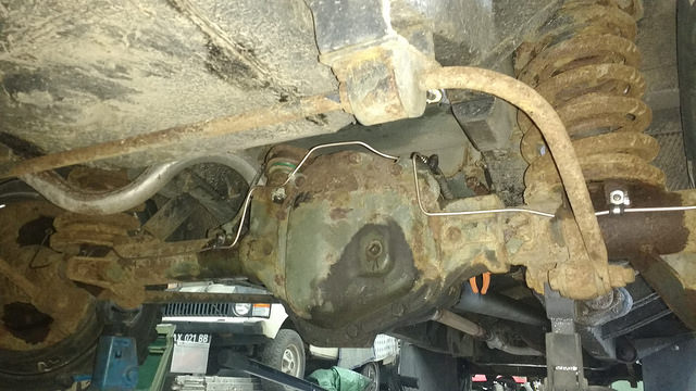
One of the rear axle brake lines on the 127 was looking a shade… (drum roll)… rusty.
Wow. It’s almost like that’s some sort of a running theme.

Thankfully brake line replacement is a fairly quick job to do – the rear axle lines in particular are easily accessible and not very long or complex.
You can buy steel lines as replacement parts and simply replace the old ones.
Problem with that is that you need the exact part every time, which isn’t too handy if you need a pipe in a hurry. It’s also more expensive and less fun, so I prefer to keep a roll of pipe and a box of nuts handy and make lines up as required.

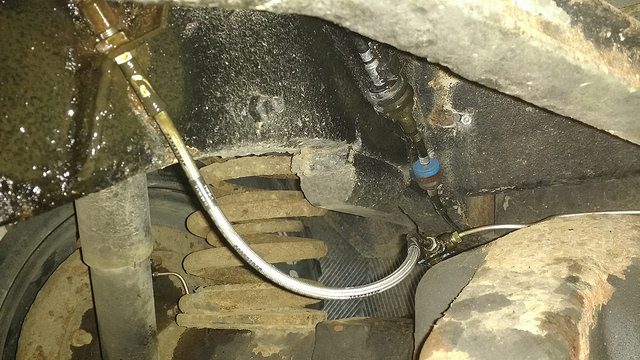
On the rear axle of all non-ABS Land Rovers the setup is pretty much the same. There’s a t-piece on top of the diff that splits the supply from the flexi line into two – one for each rear brake. The hard lines run from the t-piece to each brake cylinder/caliper.
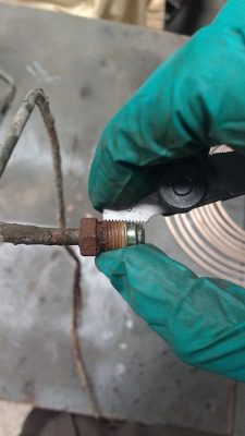
After clamping off the flexi line, first step is to undo the fittings (called nuts, despite not actually being nuts) on the t-piece and at the brake cylinders/calipers. Clamping the line stops all the fluid falling out – this is advantageous if you don’t want the system to fill with air while you’re replacing the lines.

Note one of the few legitimate uses of an adjustable spanner. Horrible things. James May had it when he called them the tool of the charlatan.
There should also be some steel p-clips holding the lines on. These ones wouldn’t budge so had to be ground off and drilled out.

Once removed, the old line can be used as a template to make a new one. If it had to come off in bits you can make new lines up on the vehicle, but copying a template line is quicker.
Brake pipe is universal – whatever age Land Rover (or indeed any other car I’ve encountered) it is, it’ll take 3/16″ OD pipe. It never went metric, despite changes in the brake nut threads.
Pipe on the roll can be had in either copper (which you don’t want) or cupro-nickel (which you do). Cupro-nickel is a copper-base alloy with greater yield strength and corrosion resistance than copper.
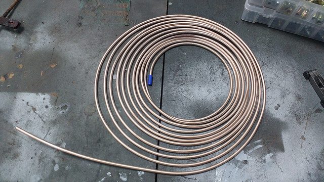
It can be roughly straightened out by hand. I like to run a brake pipe straightener over it too, to get rid of any wee kinks for a tasty finish.

Using the old line as a guide, the new line is then cut to length. Slightly too long is better than slightly too short, it can be trimmed later!

Lines should be cut with a pipe cutter for a clean edge, then chamfered (on the OD and ID) to get rid of any burrs.

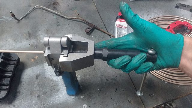
Once one end is prepped you can flare it. It’s a good idea to fit the nut first, as it won’t fit over a flared end. Admit it, we’ve all done it…
Fittings/nuts are a potential minefield. Older pre-metrification (probably not a real word) Land Rovers *should* have 3/8″-24 UN threads (that’s 3/8″ OD, 24 threads per inch). Later ones *should* have M10x1 (that’s 10 mm OD, 1 mm thread pitch). The metric equivalent of a 3/8″-24 UN would be M9.525×1.0583, so slightly smaller OD and slightly coarser pitch. Best bet is to measure what was on before, ideally with a thread gauge. Some parts are interchangeable with older/newer ones, and you never know what’s been swapped out in the past.
A 3/8″ male thread will go into an M10 female thread, but won’t be adequately strong. It’ll also feel really loose, so hopefully would be noticed before torquing the connection up. An M10 male thread won’t go into a 3/8″ female thread.
Cheap flaring tools are pants, so it’s worth paying a bit more for a good one. The same could be said of most tools, but it’s really noticeable with flaring tools. I use a Sykes-Pickavant Flaremaster, which I’d have no problem recommending. This one came as a kit with pipe cutter, bending pliers, deburring tool etc. You can spec the kit up how you want it if you want to be able to do different flare types and pipe diameters. You might need a larger diameter to do clutch lines, for example.
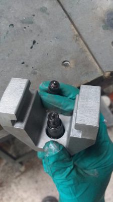
The brake line flare could be either DIN or SAE flavour. Best bet is to copy the type of flare on the old line. A DIN flare has a flatter shape where the fitting butts up against it. You can see the two shapes from the two dies in the flaring tool. SAE top, DIN bottom:

The pipe gets clamped in the main body of the tool, end flush with the flat face.

You then attach the appropriate die to the piston.
This application requires a convex flare. With this tool that’s a single-operation flare (OP1). The OP1 die (fitted to the piston here) gives the convex flare.
Some pipes (usually, but not exclusively, used with female threaded nuts) require a concave flare. Concave flares with this tool are two-operation jobs; you do an OP1 flare then re-flare the same end with a different die (OP2) to get a concave shape.
The piston assembly slips on the main body of the tool, then the handle is wound in until the o-ring just bottoms outs. This is super easy, there’s a hydraulic bearing in there to keep friction low.
That’s it, flare done.
You can get all sorts of fancy pipe bending tools to bend the line into shape. They tend to be quite cumbersome though – mine never leaves the toolbox. I’ve had the best results with the basic set of pipe pliers that came with the flaring tool kit.
Bending by hand around a good ‘ol fashioned socket works well too.

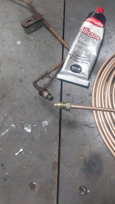
New lines made up and reattached:

The pipe nuts don’t need to be torqued up particularly tightly, but they will need quite a few turns at ‘almost there’ torque, to deform the flare a bit more to create the seal. Cupro-nickel lines feel quite different to steel lines in this respect.
I also replaced the flexi line while I was in there (quickly, so that all the fluid didn’t fall out). The flexi lines are pretty much consumables, so if the system’s going to get bled anyway it’s worth fitting a new one.
System bled and checked for leaks? Sorted.