First things first. ‘Deep dish’ or low-offset rims look awesome. Fact*

*By ‘fact’ I of course mean ‘opinion’, but hey, this is the internet – let’s not split hairs.
Alas, original-style rims with a tasty offset were used only on a select few models. This makes them rare and expensive.
So where does that leave me? Well, I’ve got a spare set of 5.5″ tubeless rims, and a desire to experiment with wheel banding.
The idea with banding is, the outer part of the wheel rim is cut off, then a ring of steel is welded in between the two halves. This widens the rim and reduces the offset. The end result isn’t quite the same as the likes of a forward control rim, as the rim will be wider overall – but it’ll still look pretty kewl.
I chose tubeless rims for this project, for two reasons:
- Convenience. I’ve had far fewer punctures running tubeless than running tubes, so I’m leaning toward tubeless whenever I change a set of tyres
- Safety. Any cracking adjacent to the welds either side of the welded-in band would result in air leakage in a tubeless wheel – this would alert me to the failure before the crack had a chance to propagate right around the wheel. Sudden failure of a banded wheel could be deeply, deeply unpleasant, so having advance warning seems like a good idea.
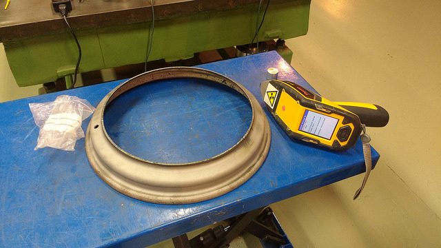
Here’s the starting point, one of a set of four bog standard Defender rims. Five would have been better, I’m still hunting for a fifth as a spare if anyone has one going…?

Part number RRC507400xxx, 16″ diameter, 5.5″ internal width.

The rim is welded to the nave plate (the bit that bolts to the hub).

Offset is 33 mm – so the hub mounting face sits 33 mm from the centreline of the rim, toward the outer bead. See my expertly put together sketch:

Follow up sketch, showing the effect of banding. By adding in an extra band of steel on the outer half of the rim, the offset is reduced. Dimension a between the inner bead and the knave plate is unchanged, so all of the extra width is on the outside of the rim (dimension b).

The plan is to add a 1.5″ band, to take the rims out to 7″ wide. With a 1.5″ band on the outer half, offset will be 33-(1.5*25.4)/2≈14 mm. Going much wider than 7″ would limit the rims to tyres that are larger than I would want to use – a 7″ rim is about as wide as I would want to go with a 7.5″ tyre.
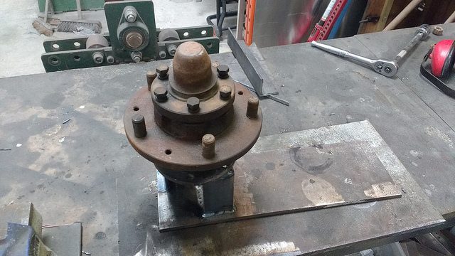
To work, then. An old hub mounted on a steel plate made a decent jig.

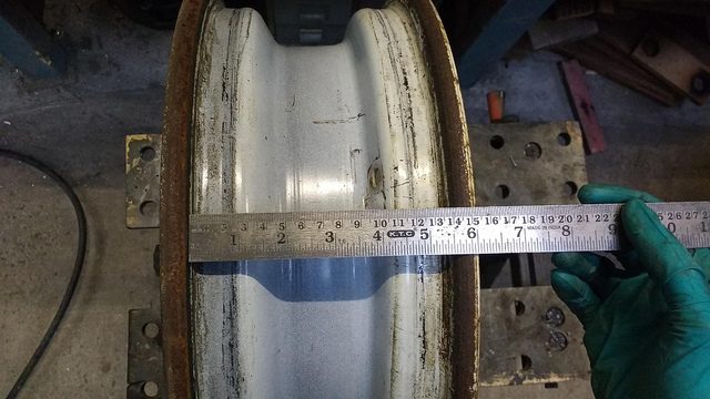
After blasting the paint off the first rim locally, runout at the outer bead seat was measured.
This came in at 0.65 mm.
I then made a holder for the plasma cutter torch and mounted it to the steel plate.


This allowed for a straight cut when parting off the outer section of the rim.
The cut was made in the small diameter section toward the centre well of the rim. On tubeless rims, there’s not really enough space to band the larger-diameter outermost section of the rim.

As the two parts of the wheel (nave plate and rim) were originally welded together, I was pretty sure the steel used was fairly bog standard. Double checking can’t hurt though, so I nabbed a quick shot of an x-ray fluorescence gun to see what the composition is.
As suspected, it’s a generic low-carbon steel. No issues welding that (or, indeed, galvanising it – I’ll be keeping that in mind…)
I acquired some suitable flat bar, and cut it to length to create the ring. Diameter of the rim midwall at this point is 344 mm, so the required length is pi*(344 mm)-1.5 mm weld gap=1078 mm.
I used a ring roller to turn the flat bar into, err, a ring. The ring roller can’t form a complete round profile from flat plate – it leaves a flat section at each end if you try:

The ends were prebent in the vice before rolling to get the correct shape of complete ring.

The shape of the ring was held prior to assembly with a root pass weld where the two ends met.

All of the parts were bevelled prior to welding. This was done with a flap disc, which takes an irritatingly long time. It’s essentially the same geometry as a pipe weld, so I used the same prep as would be used for a pipe of this wall thickness.
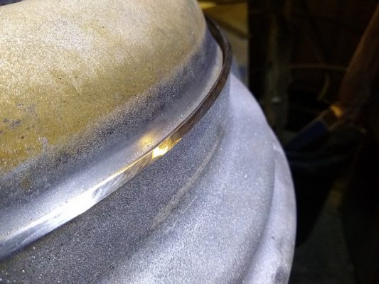
The parts were aligned in the jig and tacked in place, then the root and fill passes were TIG welded.

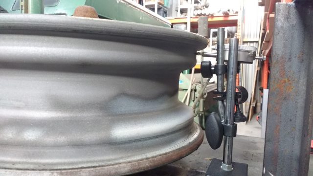
Once all the welding was done, runout measured in at 0.45 mm. that’s less than the 0.65 mm value before cutting the wheel up. Happy days.
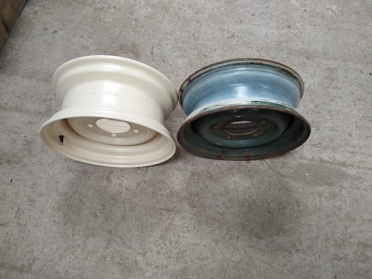
So here’s how a banded rim (right) looks vs. a stock rim (left):
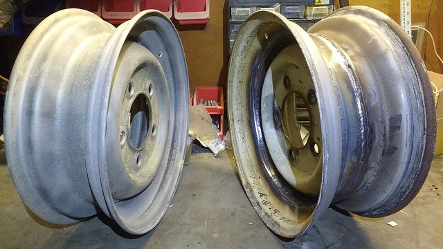
Looks pretty sweet. I’m not going to trust a banded wheel based on looking pretty sweet though. The next step was to run it past my friendly local NDE (Non Destructive Examination) specialist to check for any weld defects.
The defect I was most concerned about was cracking. Weld cracking is bad. Very bad. The radius at the end of a crack tip can be tiny, which can make local peak stresses extremely high. This is bad news for a cyclically-loaded part like a wheel rim – this is one place where you really, really don’t want a fatigue failure.
When I first mentioned to the NDE guru that I was planning on banding some rims. I was told ‘just do the one wheel first, I don’t want to have to tell you to scrap all five’. It’s nice to know he has confidence in my welding…
The method of choice was MPI (Magnetic Particle Inspection). For this type of inspection, the part is first sprayed white to provide a contrasting background.

An electromagnet is then used to induce magnetic flux across the volume to be tested. A clear fluid containing tiny iron particles is then sprayed on the surface of the part.

A defect in the examined area aligned perpendicularly to the direction of flux will cause flux leakage. This leakage attracts the iron particles suspended in the fluid. The operator will then see a black mark or line of iron particles at any defect.
The process is repeated a few times, with the magnet orientated differently to catch defects running in different directions.
In this case there were no indications, so the welds got the seal of approval. Success!
Next step: complete the set.
I improved the jig setup a bit to speed up alignment, but otherwise the process for the other rims was similar.

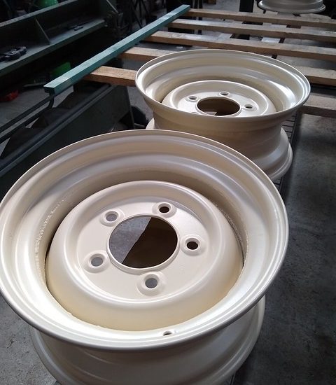
Behold, a set of four:

And painted:


Done.
By the by, this is Jotun Jotamastic 90 paint, in RAL1015 ‘light ivory’. I’m trying it out as an alternative to cellulose ‘limestone’ paint, as I’ve not been too impressed with the chip resistance of cellulose. Wheels have a hard life, so hopefully the Jotamastic (which is a 2-pack epoxy) will be a bit more durable. The primary downsides are cost (my wallet actually cried a little when I paid for it) and it’s chock full of lovely isocyanates, so you need to go a bit mental with PPE if you don’t want to get horrible lung diseases. Full body cover and full-face respirator are the order of the day.
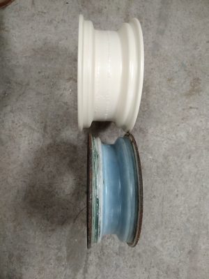
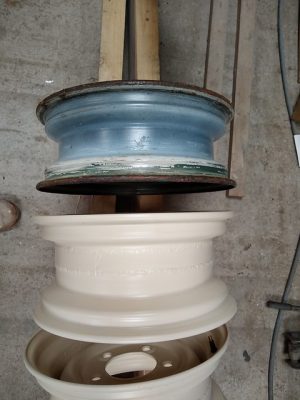
Here’s some comparisons of a banded rim vs. a stock rim.
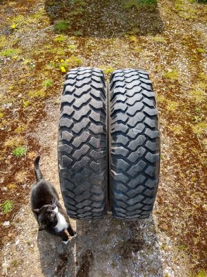
And here’s what a worn 7.50 Michelin XZL on a banded rim (right) looks like, vs a slightly less worn 7.50 XZL on a standard wheel (centre); and… Griselda. The cat. (left, obviously).
Eventually these rims will end up on the series 1, but I wanted to test them a bit sooner than that so I fired them on the 110.
The 110 with standard rims:
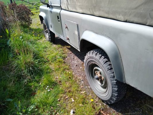
And the banded ones:

Looks fairly splendid I reckon.

I got to almost terminal velocity on a test drive (which, admittedly, isn’t especially fast with a 2.5 NAD and 1 2/3rds ratio tbox.) There was no noticeable wobbling or vibration. That’s with no wheel weights fitted – I just fitted the tyres and slung the wheels on. I’m sure they’ll take a bit more lead to balance than a stock wheel, but it seems to be not much of an issue on the 110, and will probably be even less so on the s1.